Fitting the 4L80e into a range rover
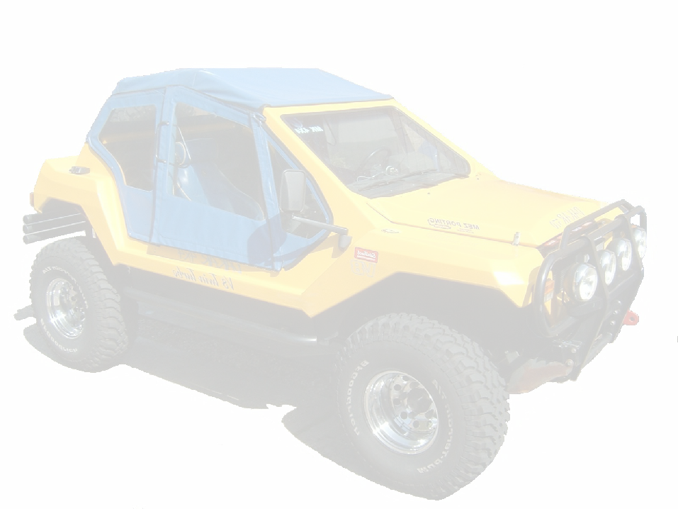
This page will document the design and installation of a 4l80e to replace my long suffering 700r4 (4l60) in my Landrover Range Rover based kit car.
24/7/2007 My Own Design 4L80e conversion for the LT230
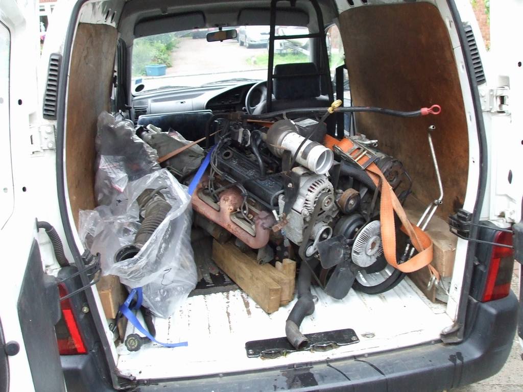
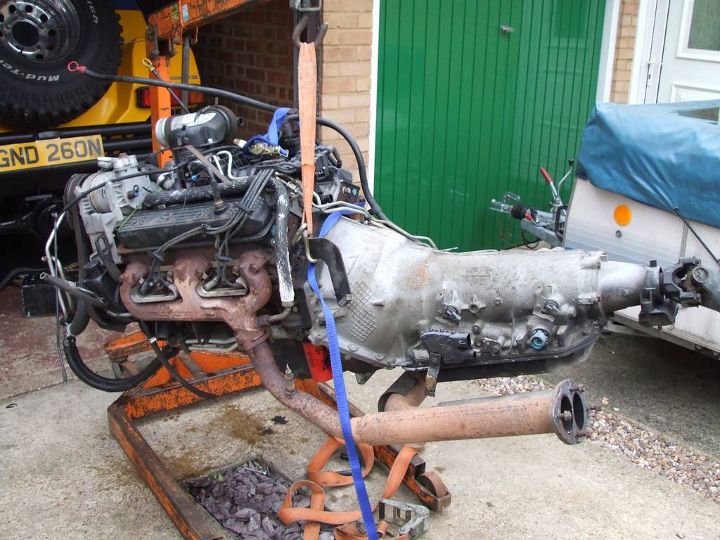
After a careful search I've finally obtained my own GM 4l80e. Its a 1996 box from some big yank truck, came attached to a 5.7 Vortec engine which is nice.
7/8/2007
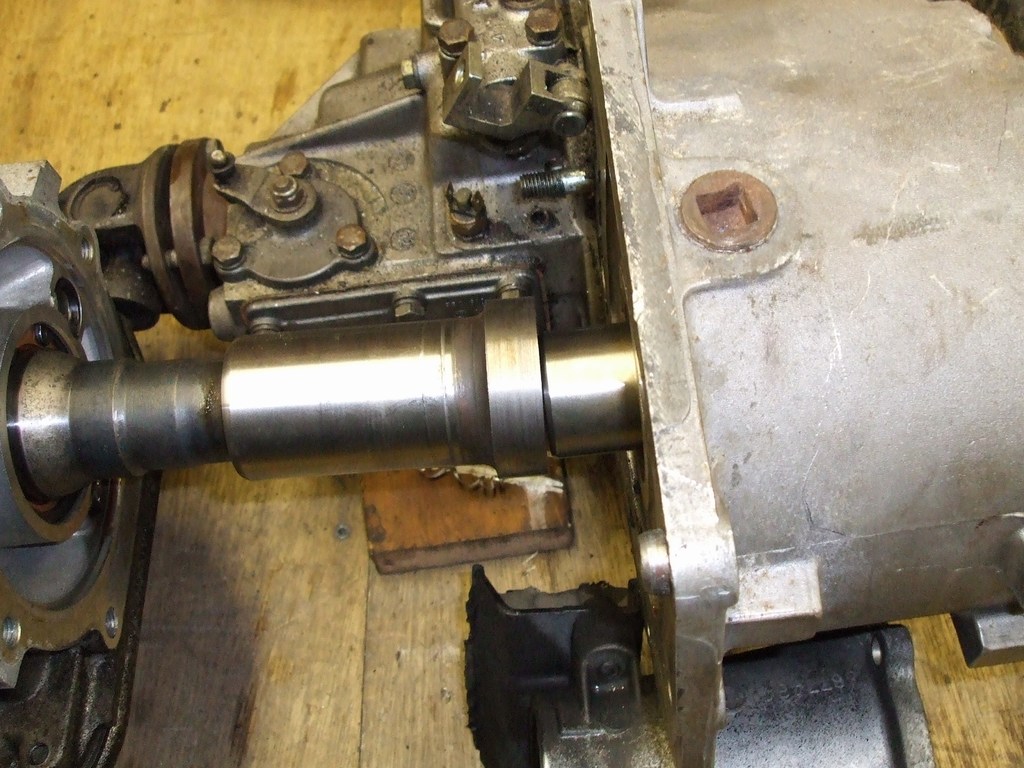
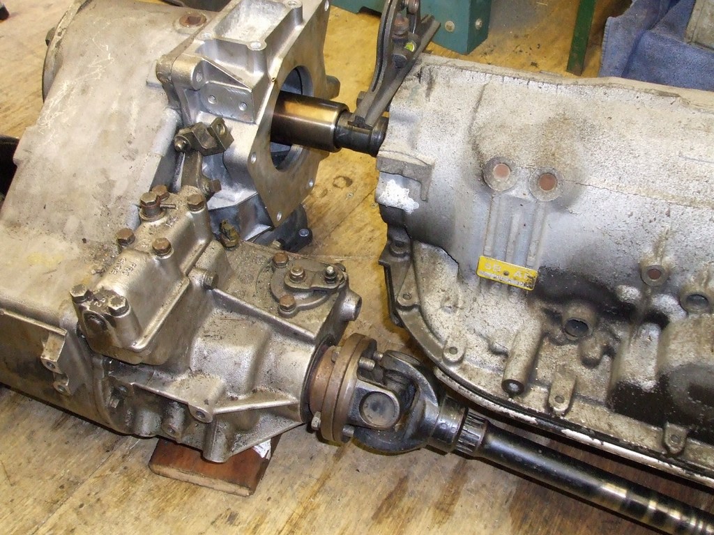
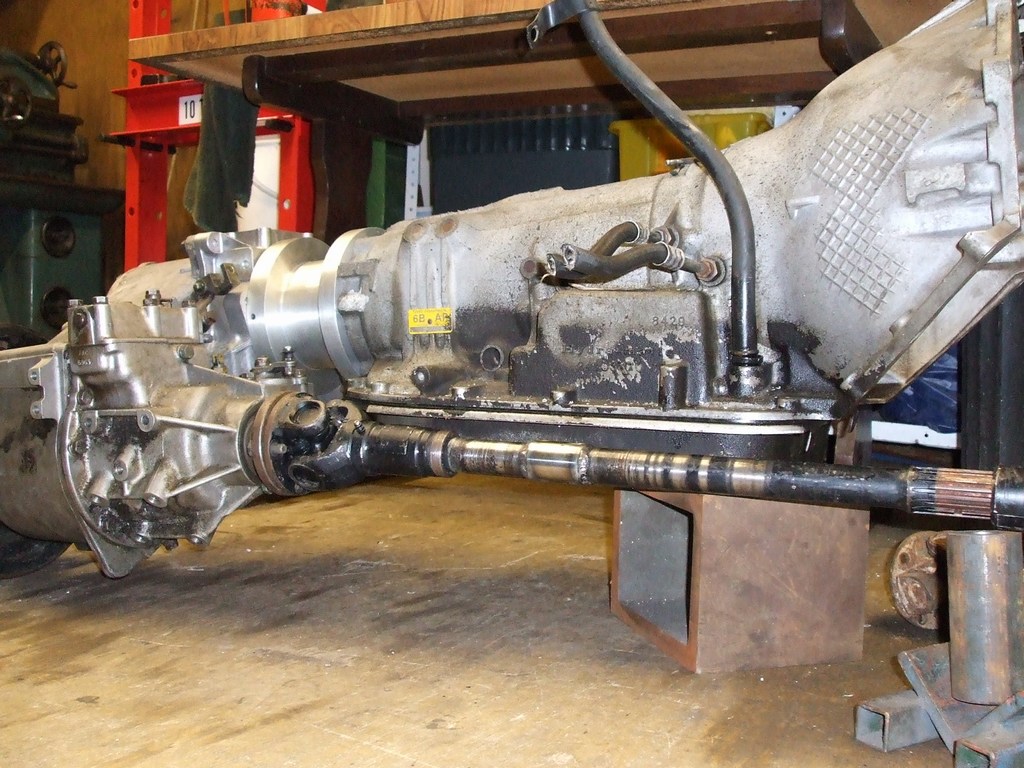
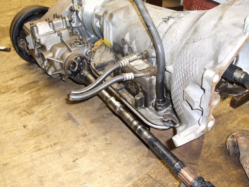
First job was to cut down the old yolk, My new bi-
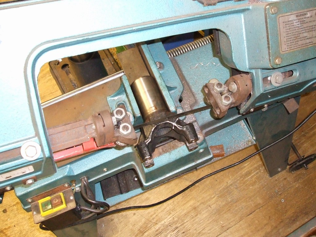
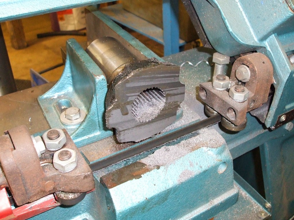
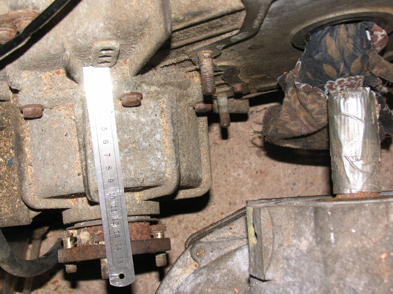
Here's a couple of shots. My overall length is 30mm shorter than the marks adapters version. I'm trying to avoid cutting too much of the floor away to fit it in.
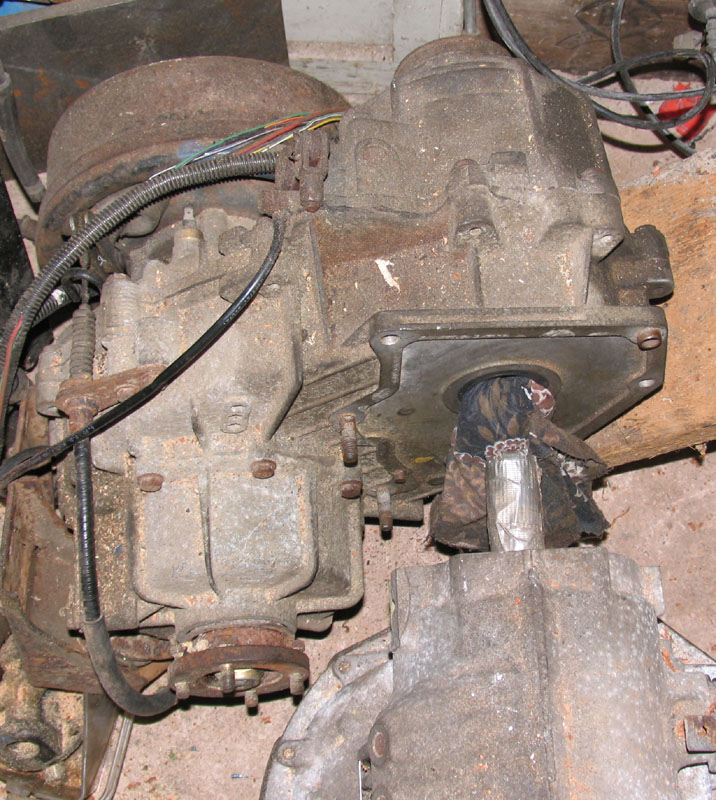
So as it stands now, the transfer box will need to go back another 40mm.
XX has provided me with photo's of the borg-
18/08/2007
Now got the LT230<>TorqueFlyte adapter (frc5622) and also have welded the shaft together.
Unfortunately I forgot to take a photo just before I welded it. The FTC5090 coupler
shaft fits inside a recess that I machined 8mm into the end of the yolk. In order
to give it more strength I machined a 16mm slot across the cast yolk, the idea is
to create a "fish-
So here's where I'm at. I'm waiting for a 7" chunk of T6062 ally and a bush and seal in order to start on the actual adapter part now.
4/9/07
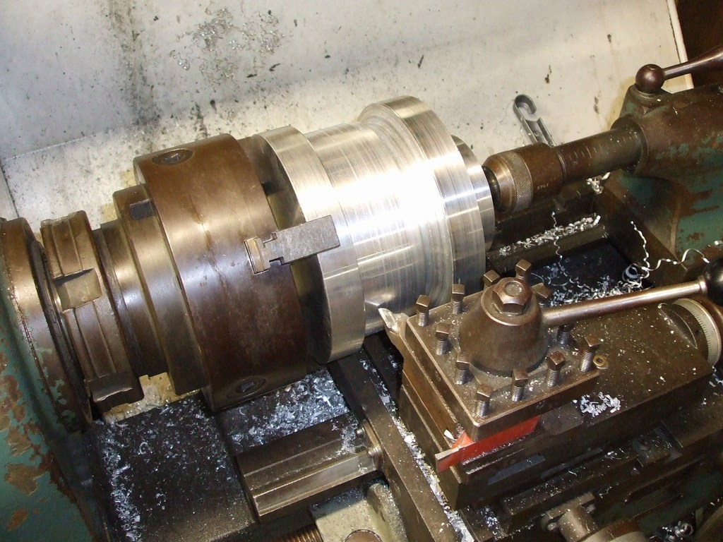
Ally turned up, squared and centered one end of it -
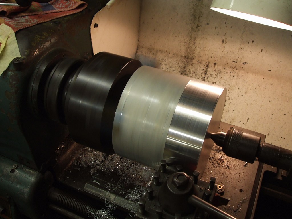
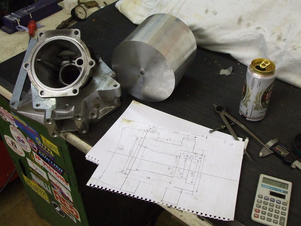
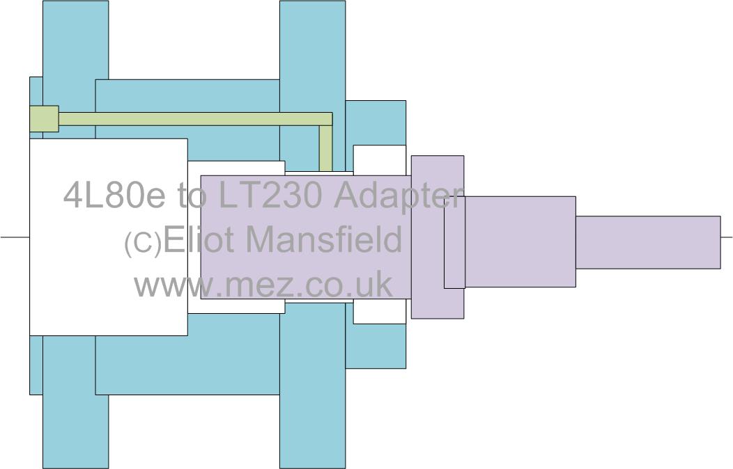
Here's the design and the beginnings of the adapter:
29/10/2007
Megasquirt guru James Murray has written code that turns a Microsquirt into a transmission
controller, Its in alpha awaiting physical testing -
Which has given me a shove to get on with my adapter, so a couple of evenings work has got it looking more like an adapter. This is long tedious work, would take 10 minutes with a CNC setup!
1st December 2007
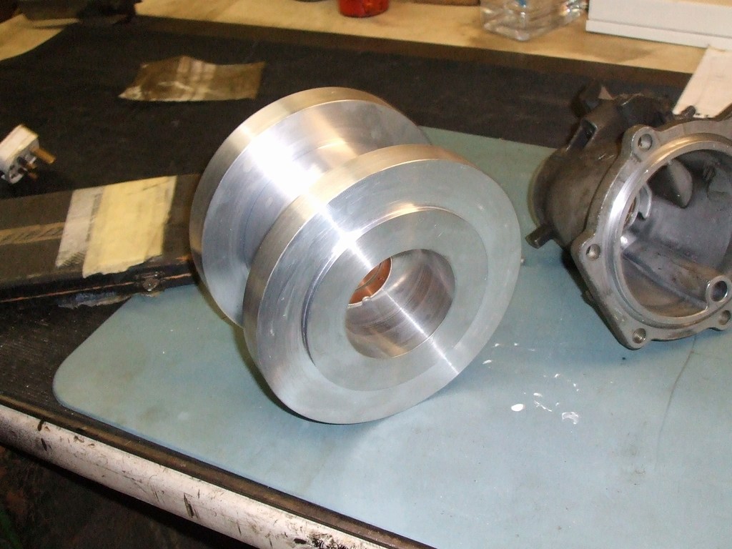
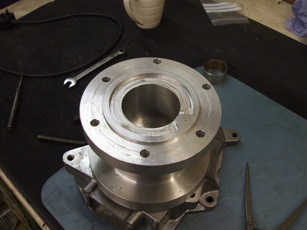
Now the 440 is done and can actually spend my time working on my own projects, got the front half for the bush and seal completed today:
9th December 2007
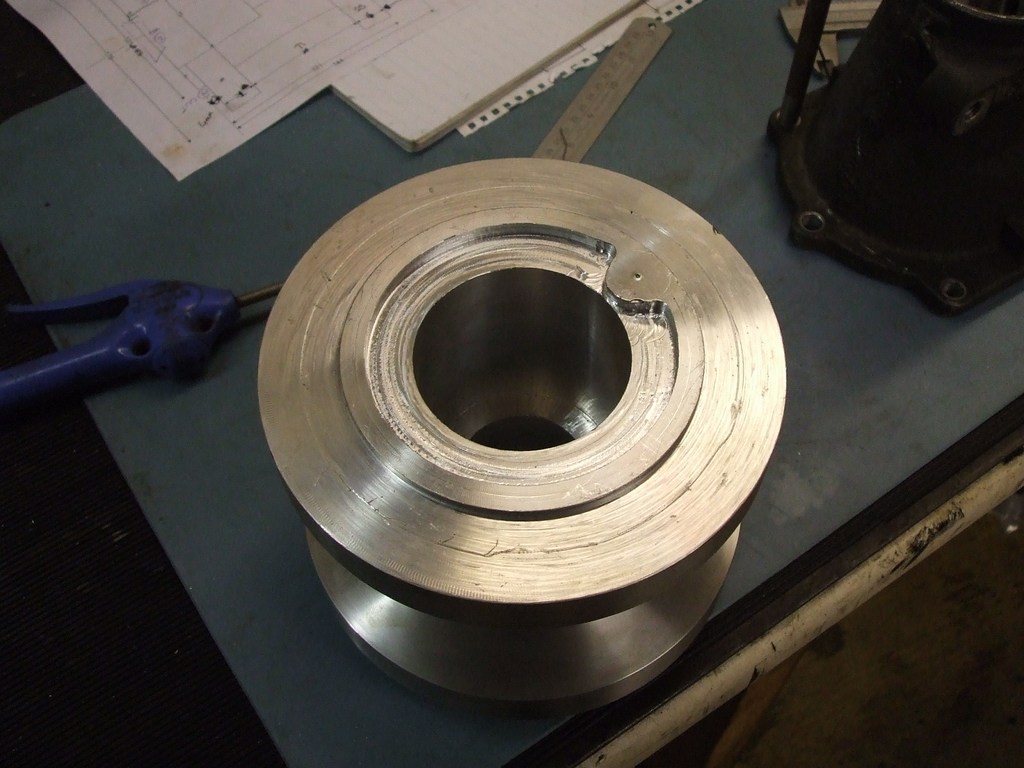
A few more evenings work, got the oil feed passageway shaped -
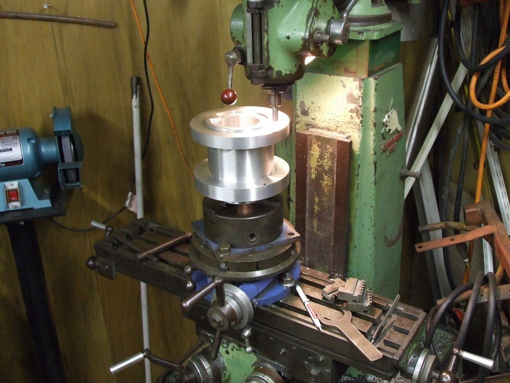
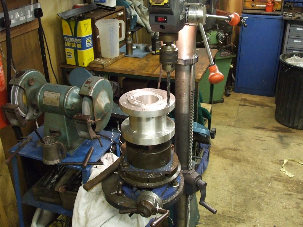
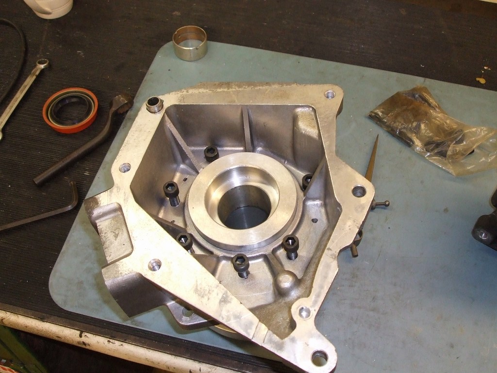
Next job was drilling the holes to attach it to the back of the 4l80e. I thought
this was going to be one of the easier parts. 6 bolt holes, 60 degrees apart -
First problem: It's too tall to fit in the milling machine with a drilling chuck
fitted, so after a few false starts I decided I would just centre punch the holes
using a very short chuck and a custom made centre punch that fitted in that chuck.
I then found out that one of the holes is 58 degrees round from the previous and
two of the other holes are on a different diameters individually -
I placed the dividing table on the pillar drill, which is less accurate than the milling machine, but the only way it could be done. Thankfully I got the holes in the correct location first time.
Next job was 6 threaded holes at the other end to attach it to the LT230 adapter, which was easier.
 24th December 2007
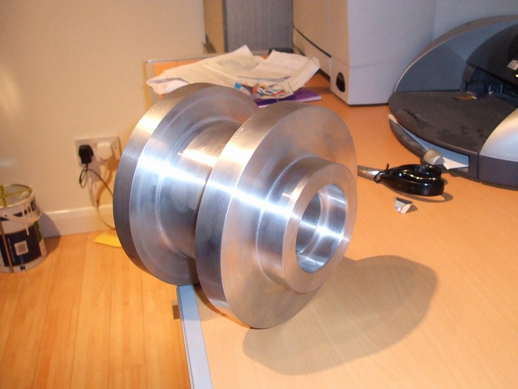
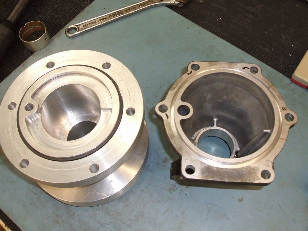
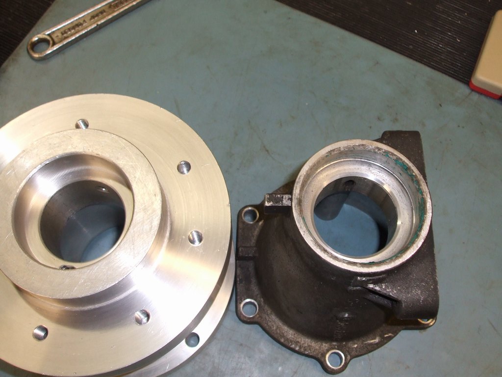
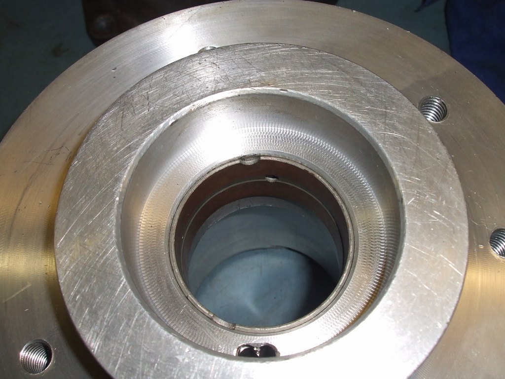
Adapter is now complete, you can see from these photos that I have duplicated the oil feed passage to the rear bushing in my own adapter.
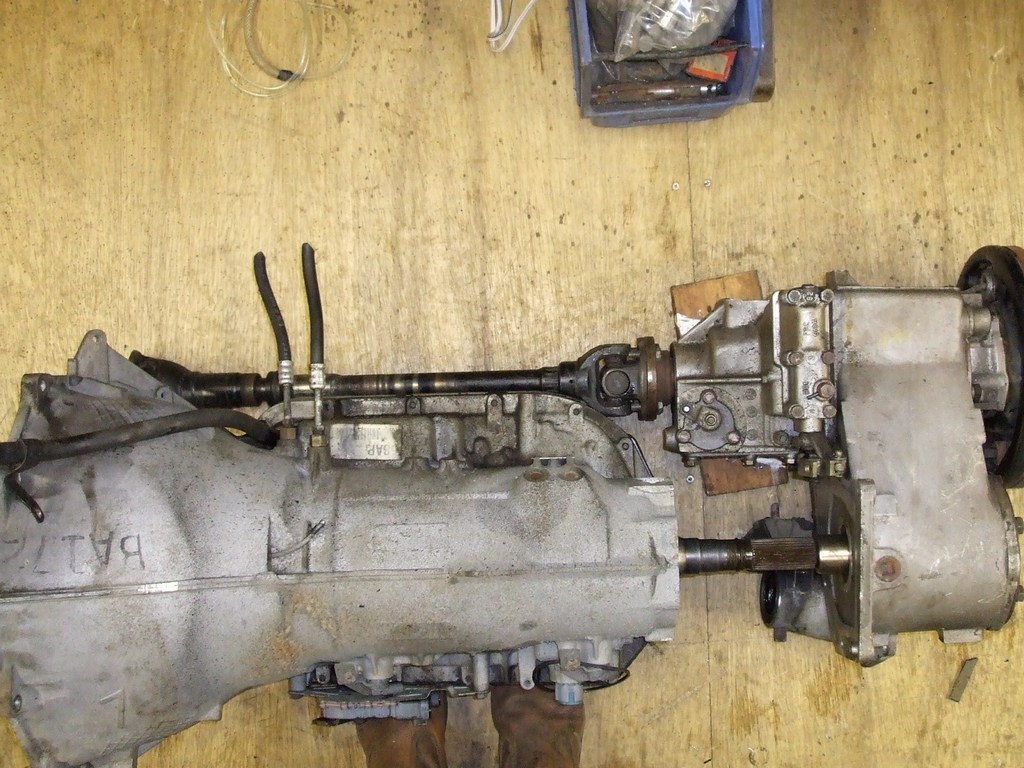
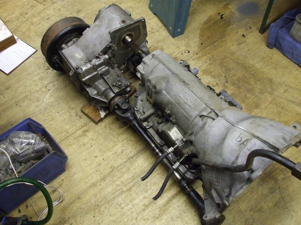
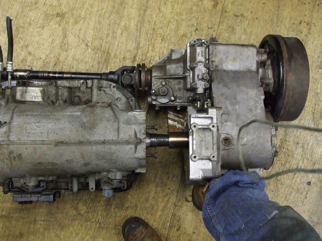
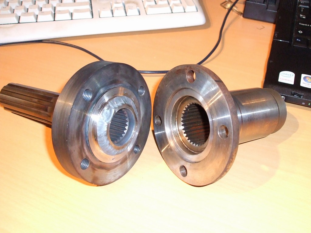
Next step is to figure out what to do with the front propshaft. This is the standard
range rover front prop, which has a 2" OD. It clears, but is very close. I could
do with a 1.5 or perhaps 1.75" one really -
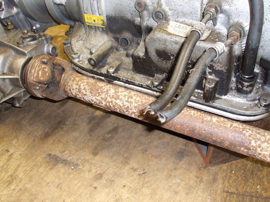
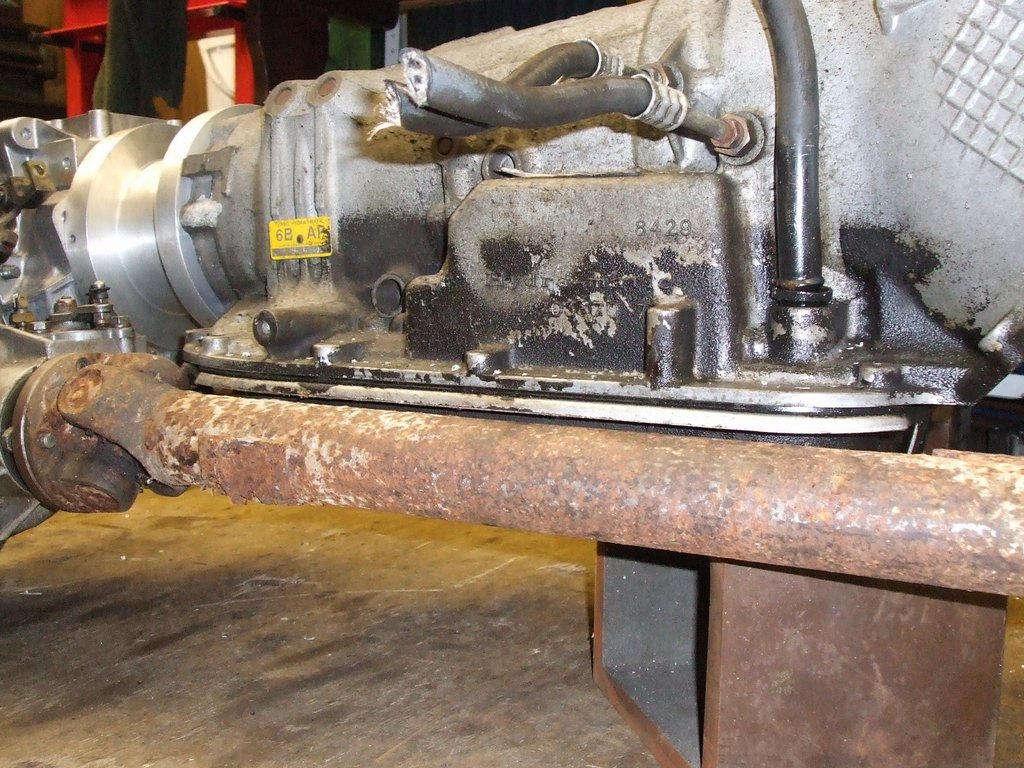
This is the solid prop used on some range rovers, the actual shaft itself is just over 1" (29mm). The widest part of the sliding joint is 1.75", which does clear.
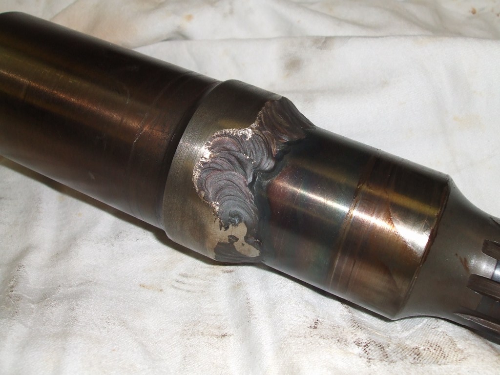
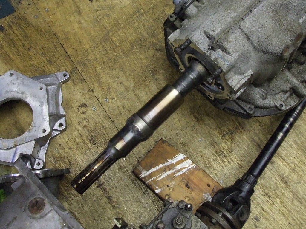
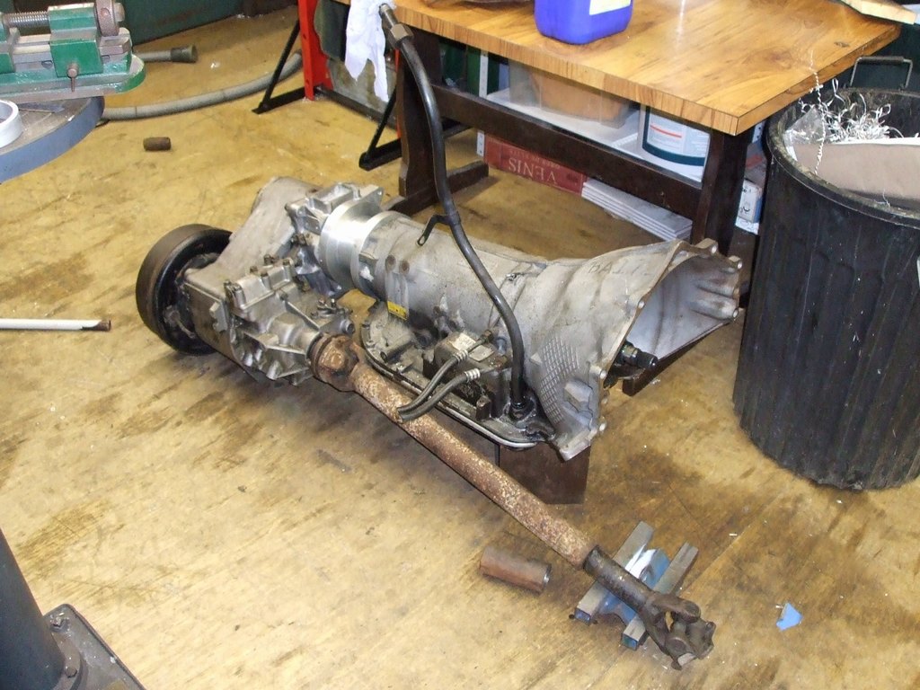
7 Feb 2008 MK2 Adapter Shaft
This is my MK2 adapter shaft. The previous one shown above was running out of true.
This was because I could only get about 8mm worth of "register" to push the two parts
into one another. I couldn't get hold of another UJ type flange -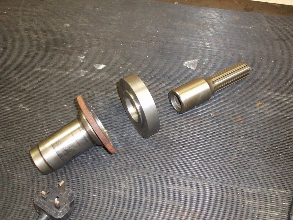
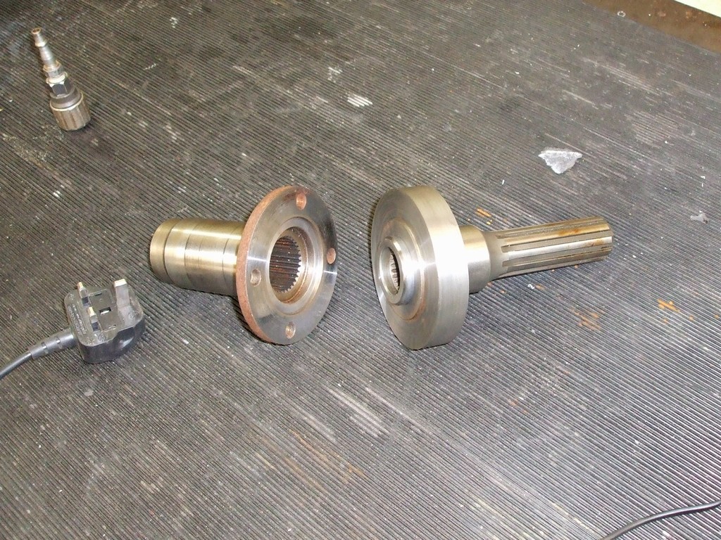
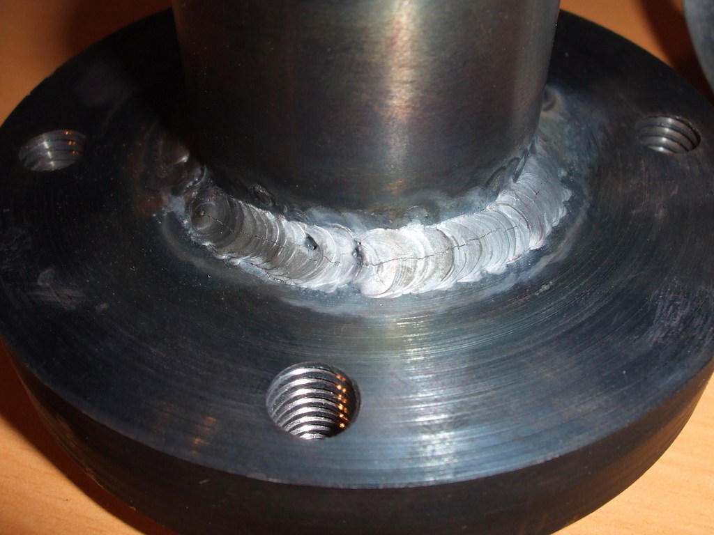
I then welded around the end of the shaft and the turned it in the lathe so it fitted into the Jag output flange.
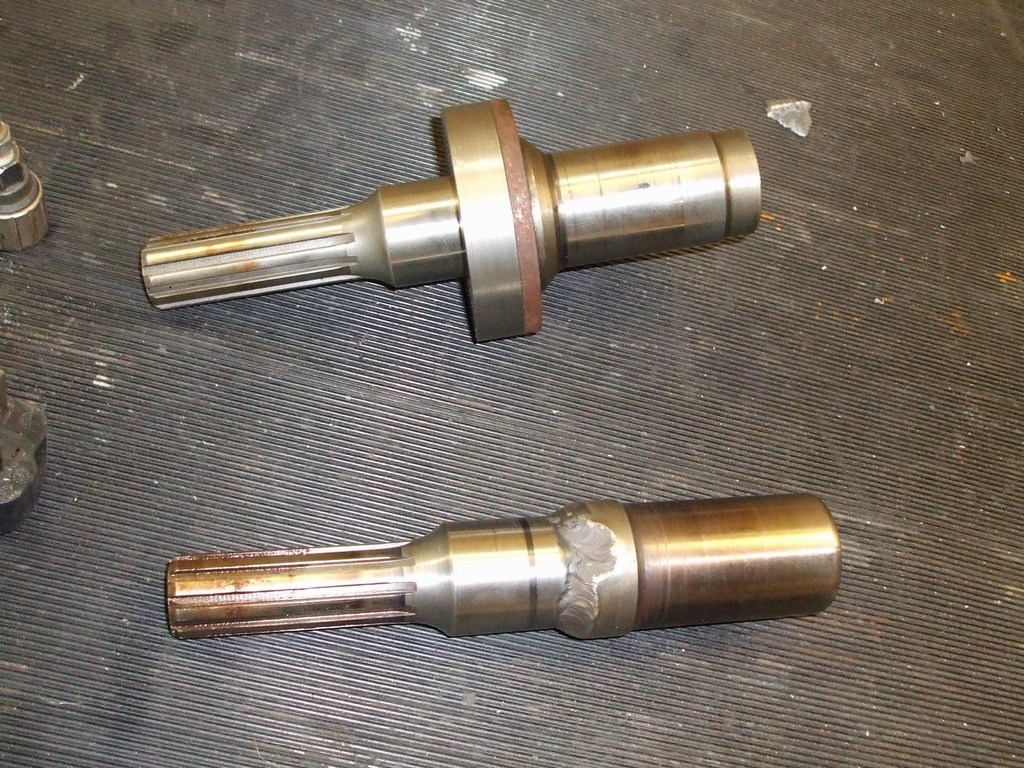
The only issue I had was running another bead around the other side of the coupler;
a crack formed as quick as i welded it -