21/11/05 Chargecooler layout considerations
Finally managed to get some cash together to carry on with the chargecoolers. Ordered 3off 100mm x 255mm 4 row water cores from Pace Products.
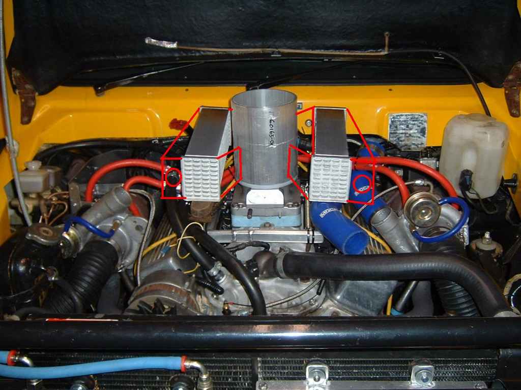
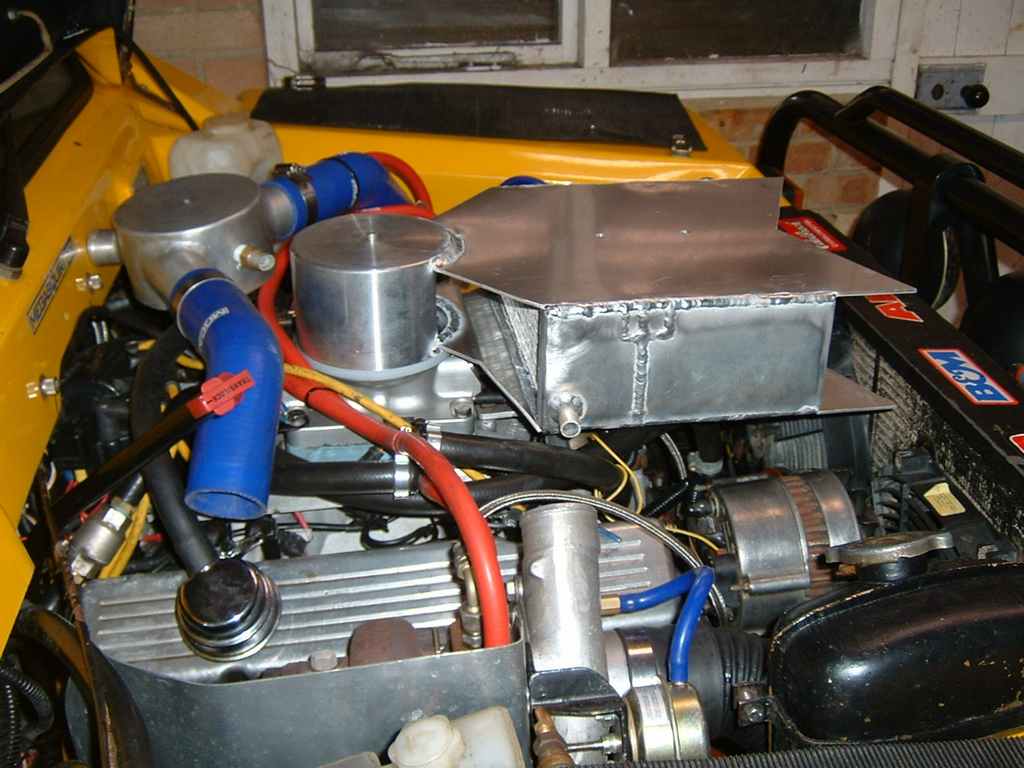
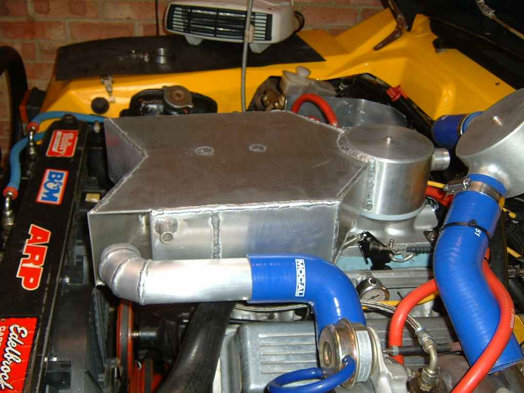
Ive decided to put the chargecooler in the engine bay rather than the inner wing,Mainly because I didn't like the look of all the charge piping going everywhere. As ever, first task was to take some digital photo's and sketch out some ideas.
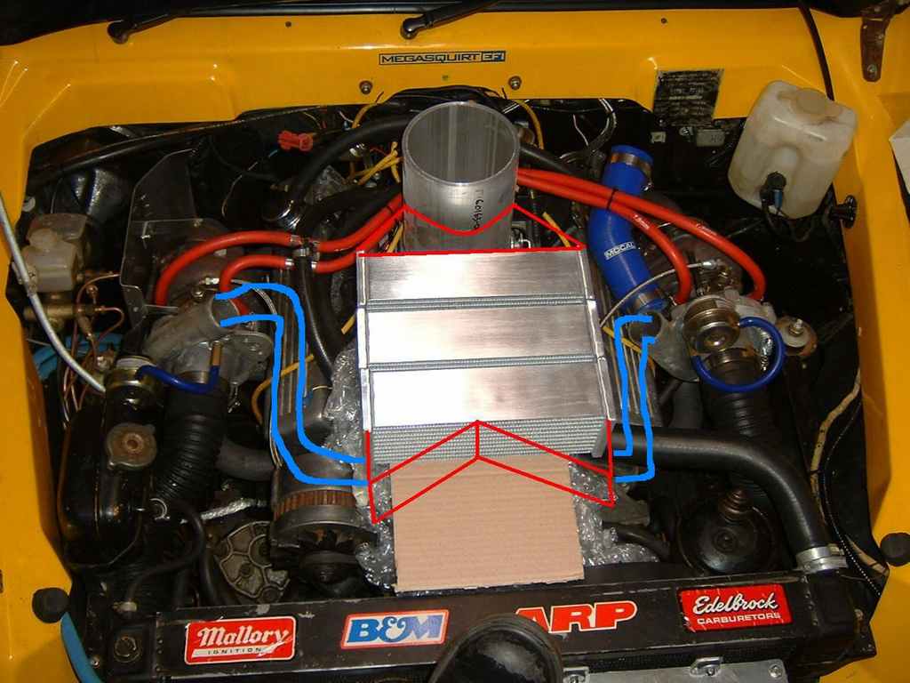
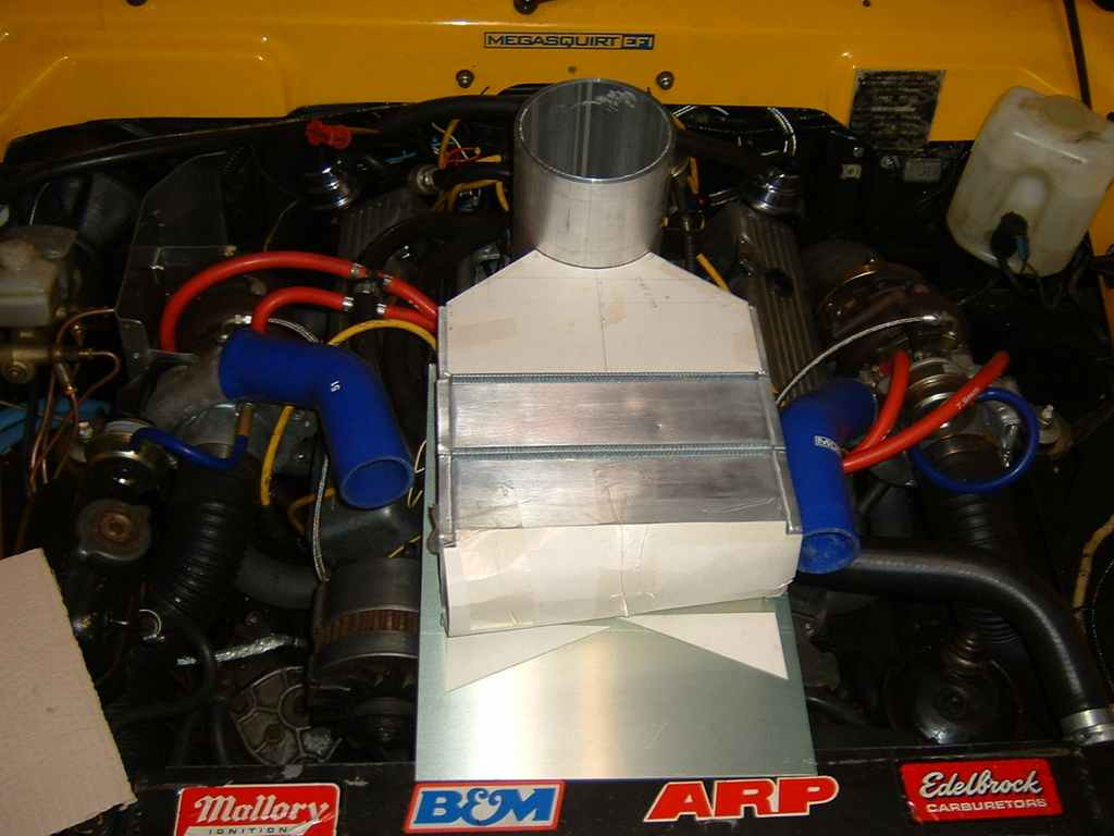
Option 1: Three cores out front:
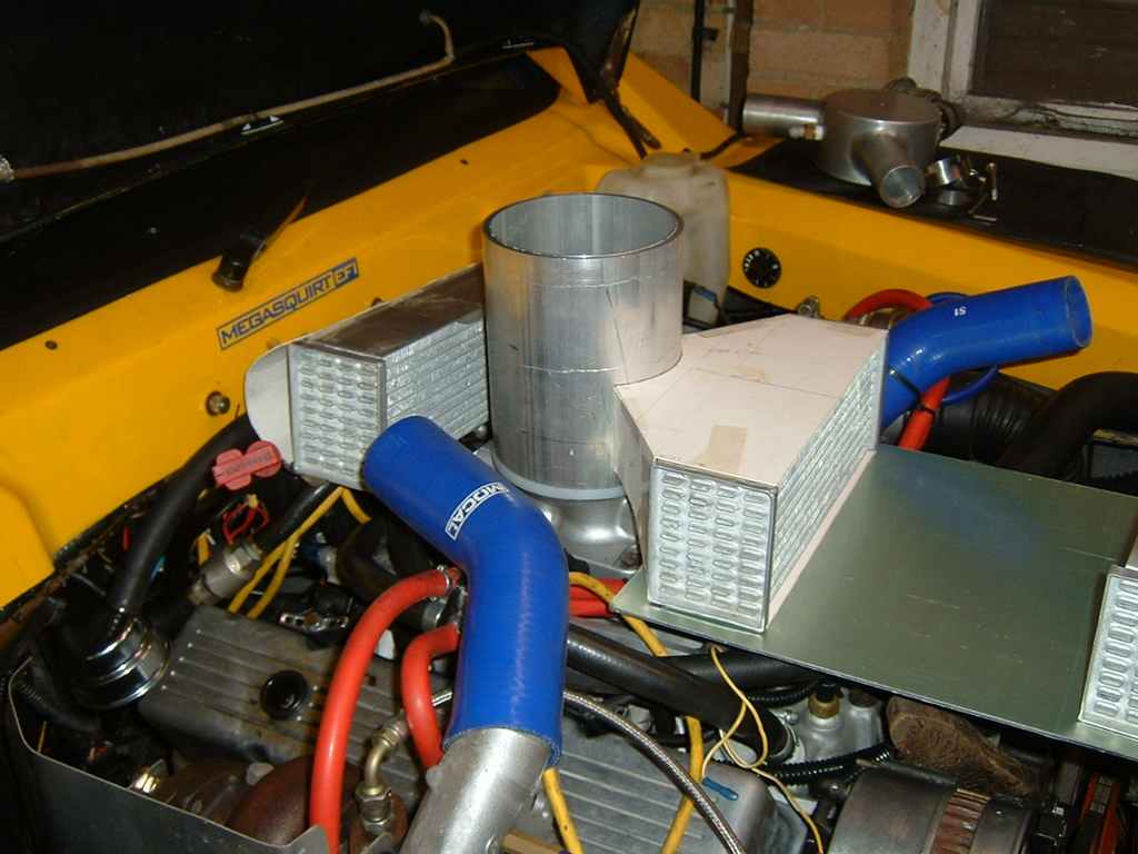
Option 2 and 3: One core either side or front and back:
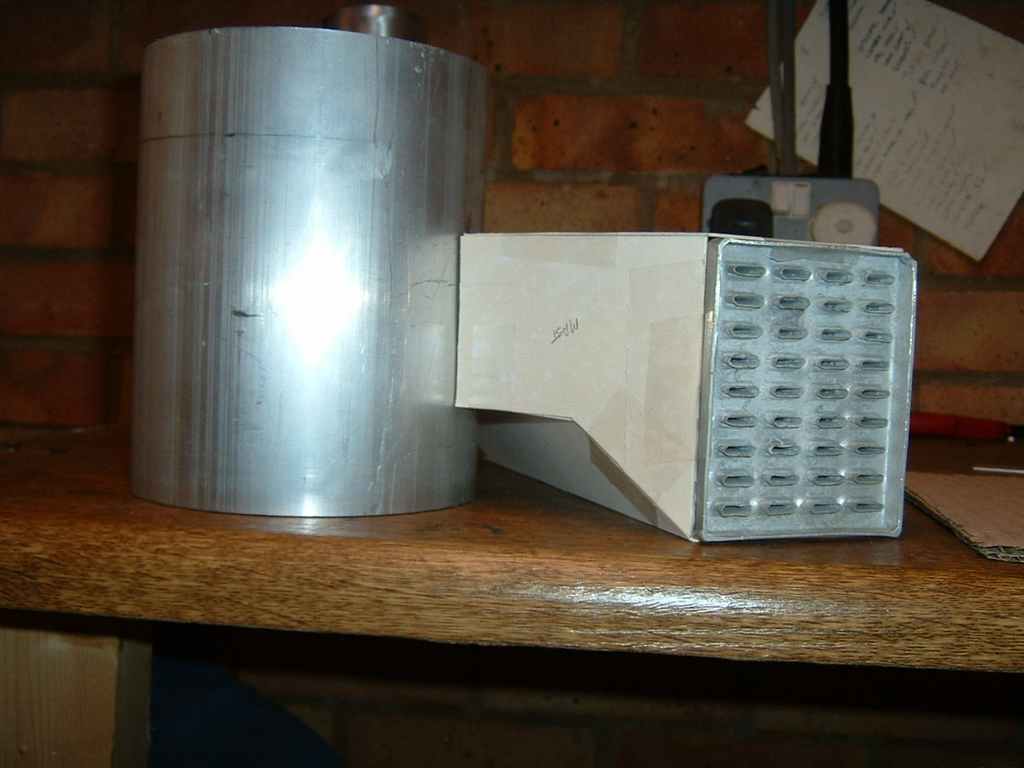
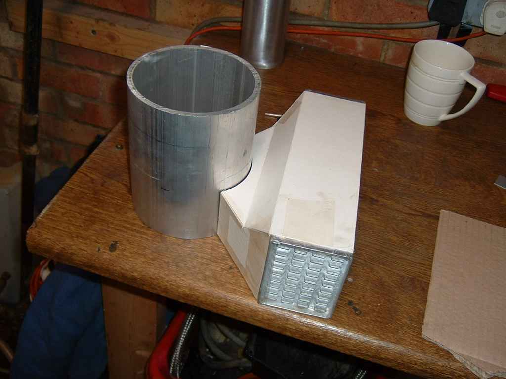
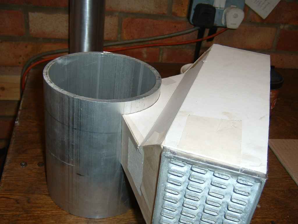
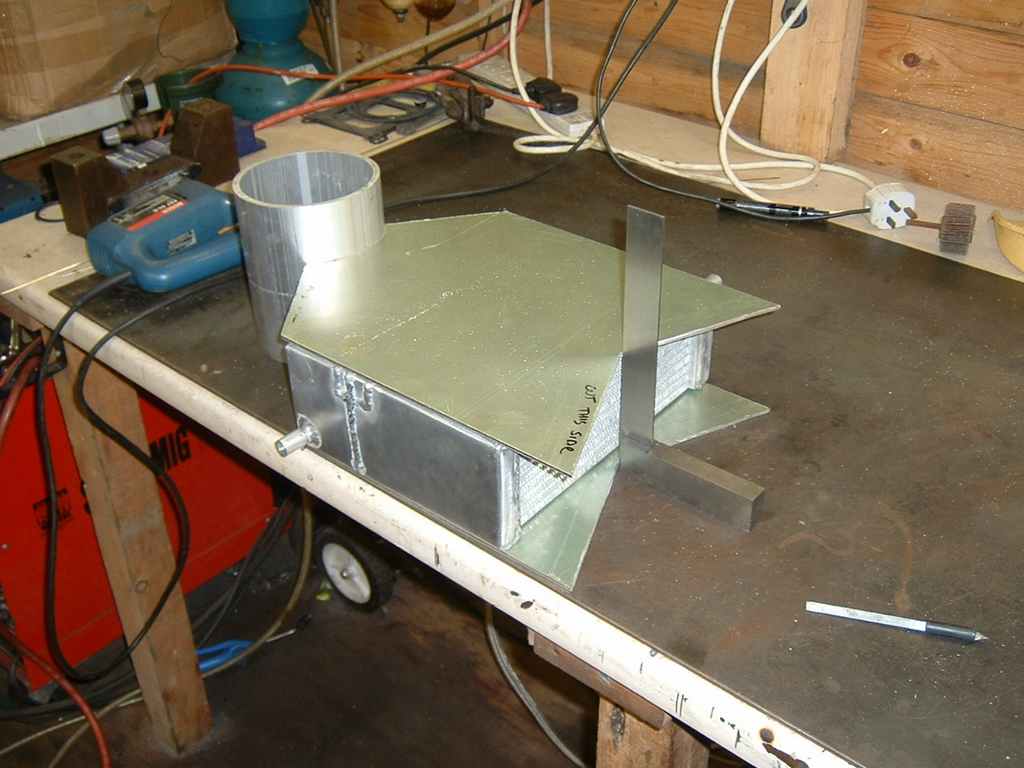
Now children, when your'e in skool wondering what's the point of trigonometry and that will never be any use to you...think again; This little creation took me ages to make because I couldn't work out how draw the angled bit on a flat piece of paper which would fold into the correct shape without any gaps.
 Chargecooler fabrication
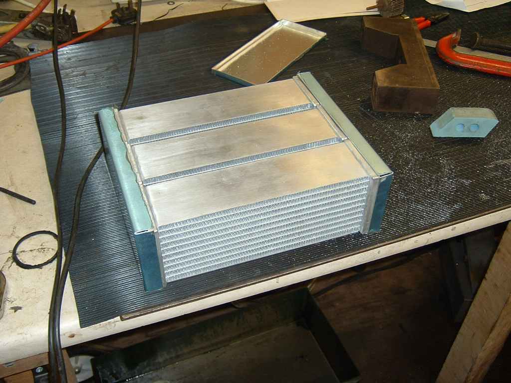
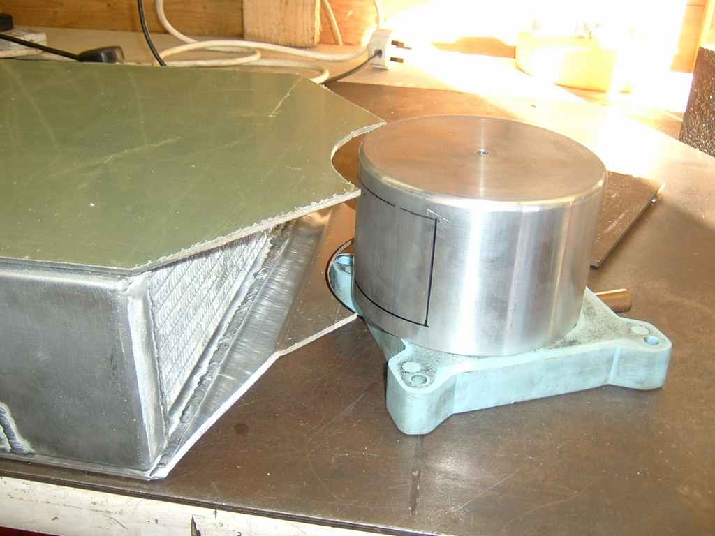
The final design choice is the three in a row design, as its the most effective.
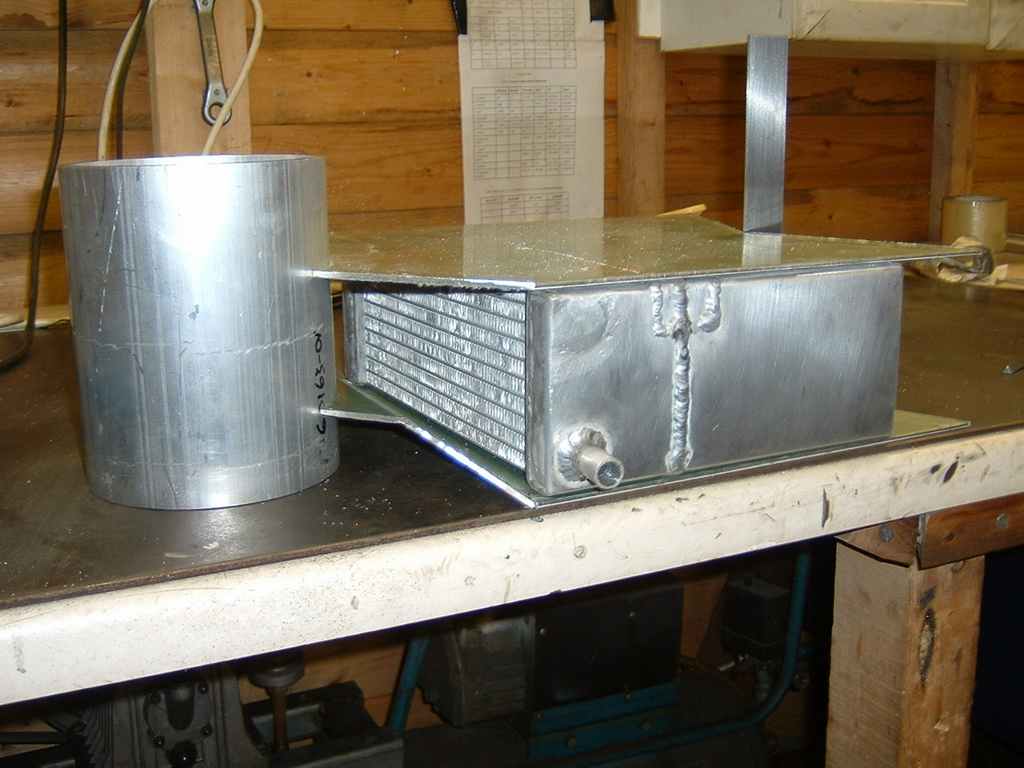
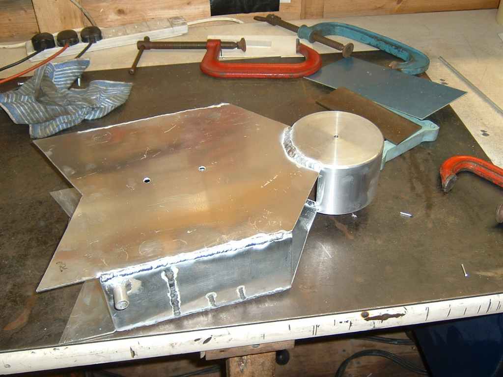
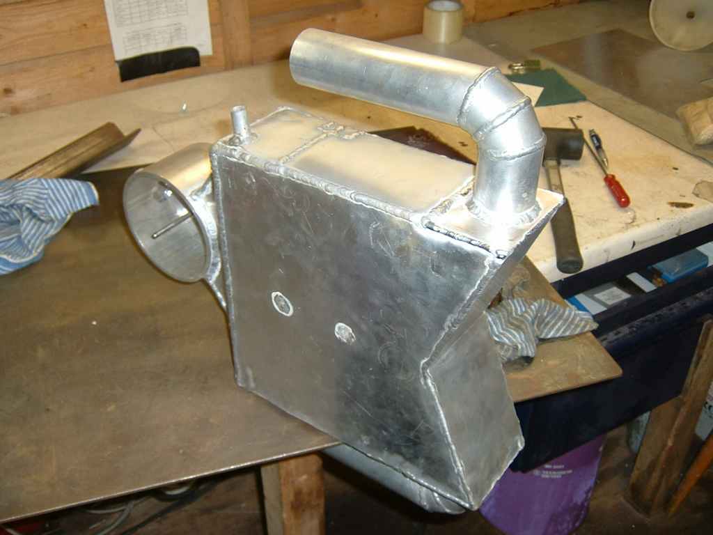
First step is to fabricate the end tanks. These are made from a single piece and
then divided up to form the compartments later.(Which doesn't seal very well, don’t
copy this idea -
Original plan was to butt-
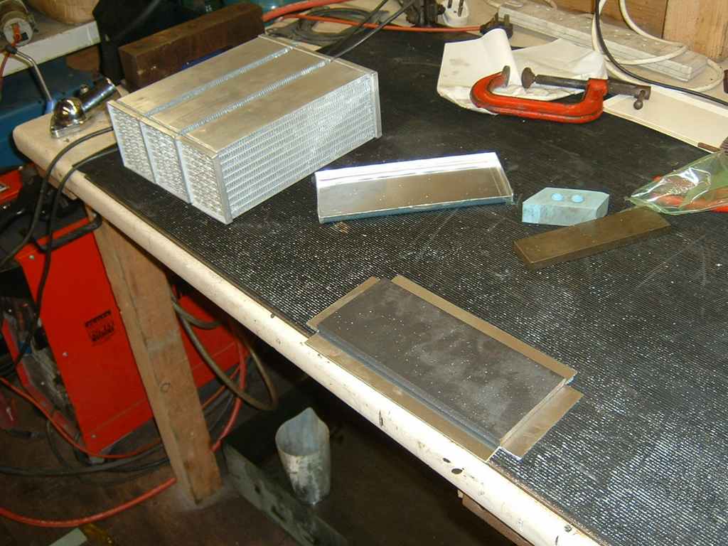
Despite cleaning the ally flanges up, I still suffered from dirty welds -
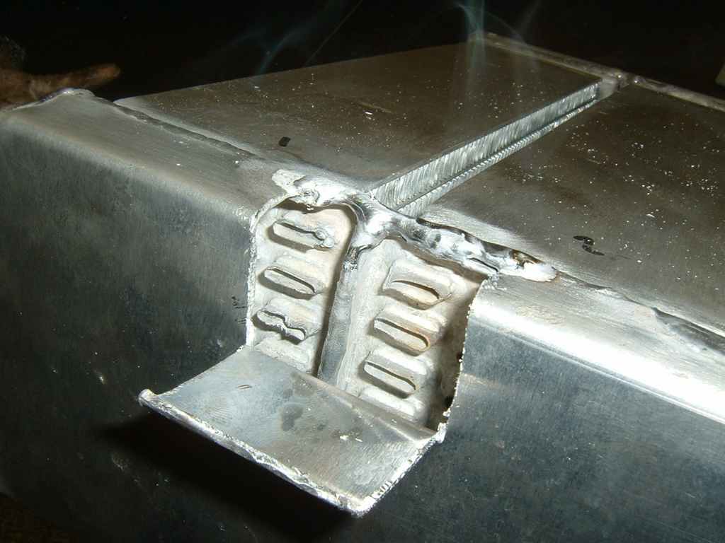
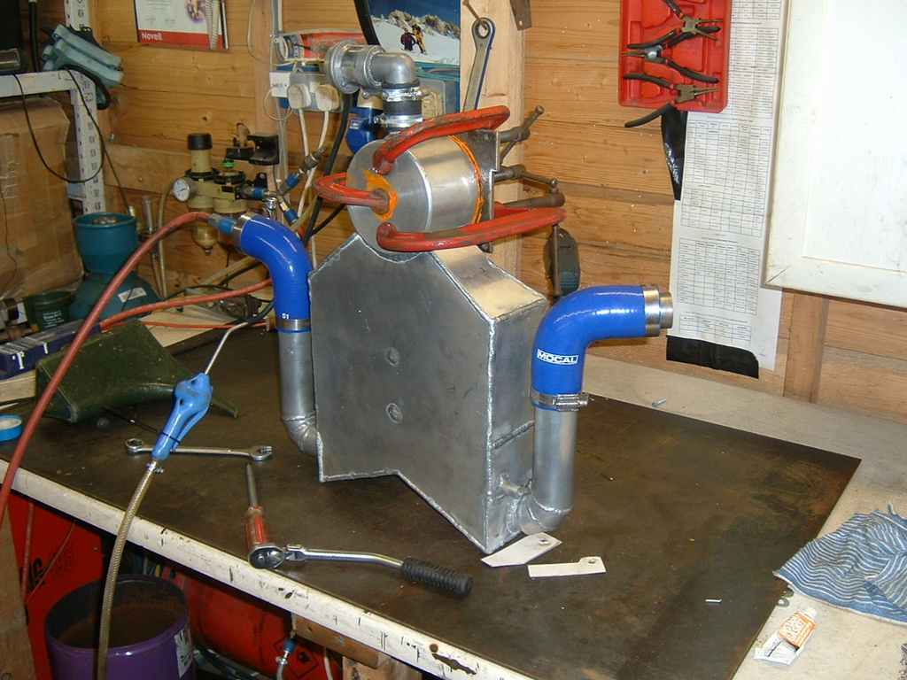
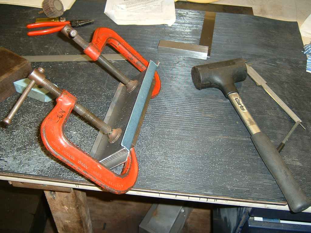
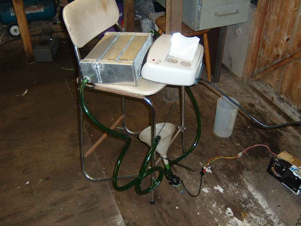
Once all the holes were patched, you cut a slot down the tank and weld in a divider to form the water compartments. Tried it out on the bench with a 3KW fan and my pump unit.
30/12/05 Charge tank fabrication
04/12/05
Cut the hole out with a Jig saw, was only supposed to tack weld it inside -
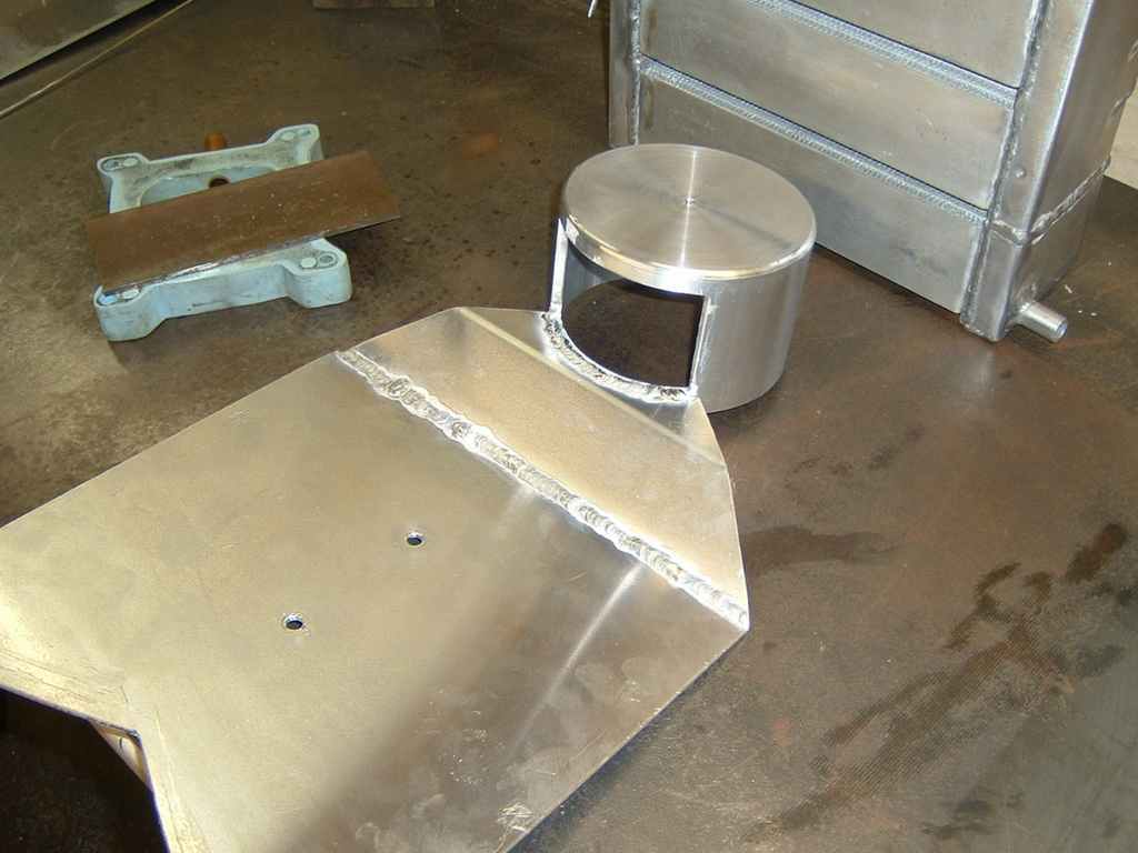
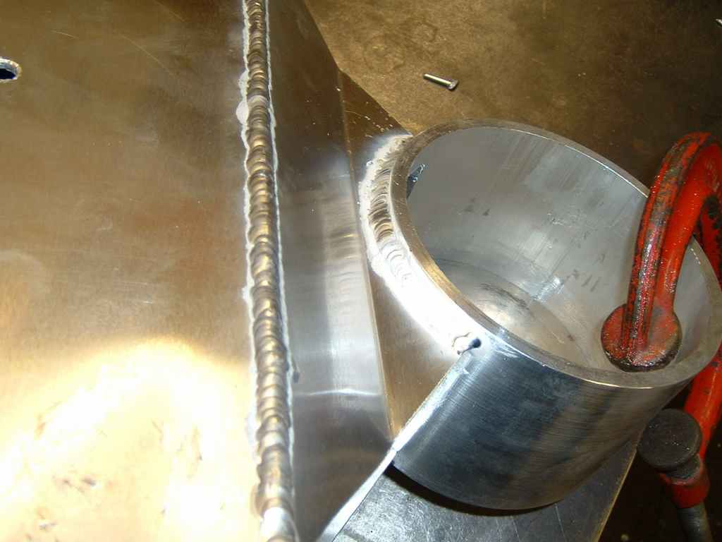
Tricky bit of welding the 3mm plate to the 6mm top-
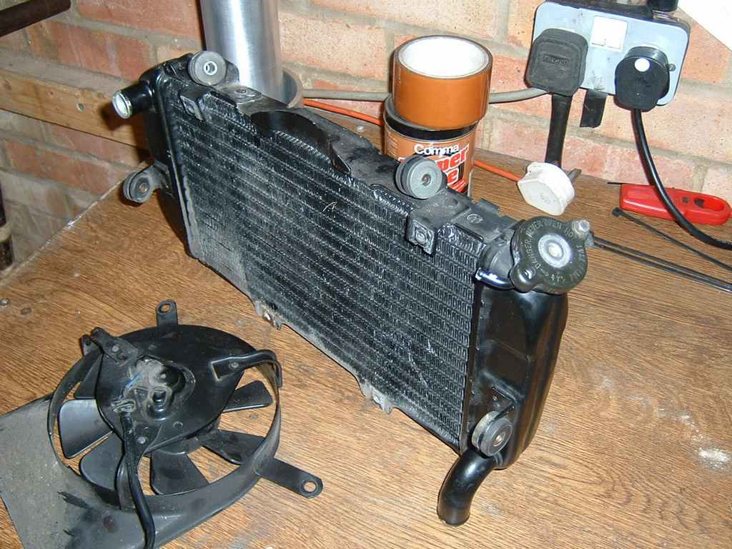
Scored a cheap motorbike radiator to use as a pre-
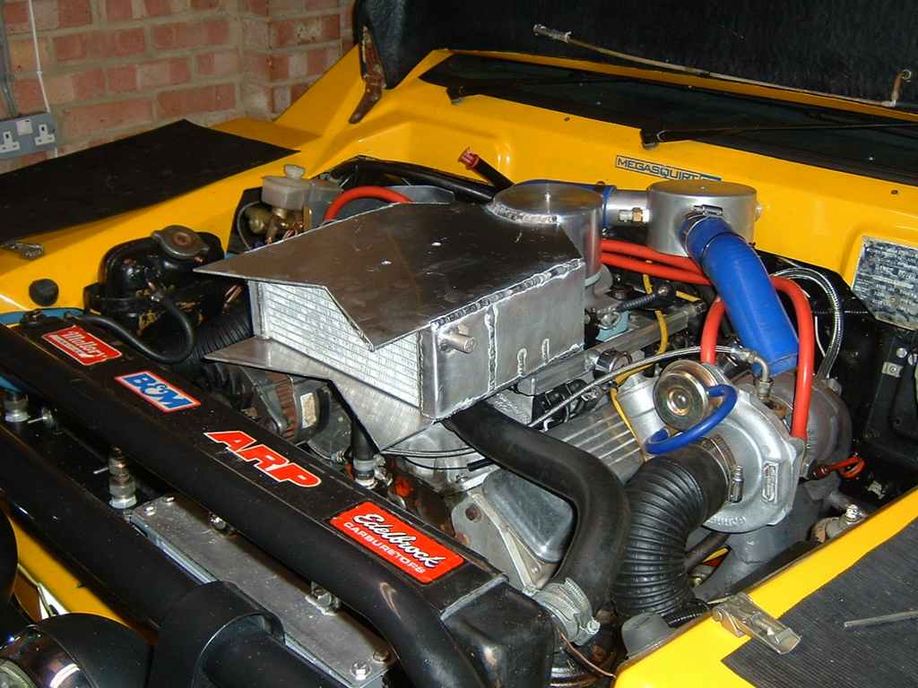
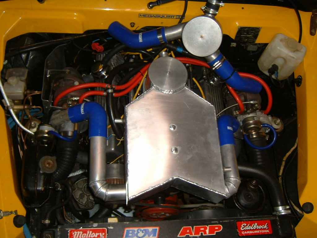
Yes, the bonnet does close!
11/12/05
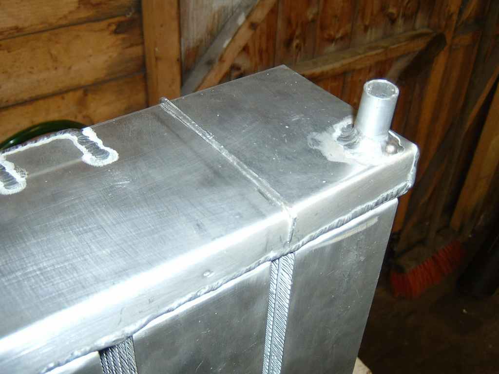
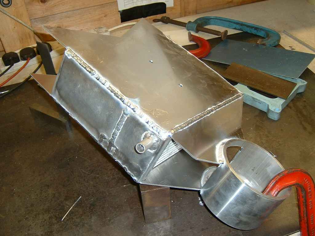
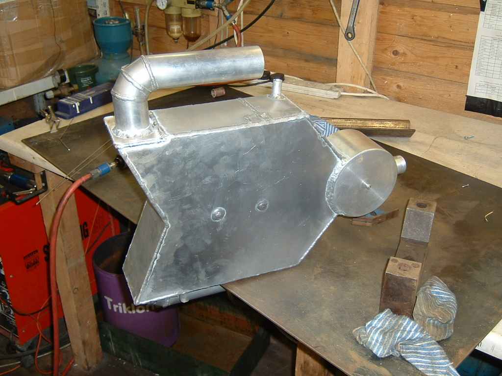
Another weekend of welding gets most of the cooler completed. Can now start on the connecting pipes.
17/12/05
Charge pipes done. Although not seen in this photo, the other side is very short which made getting the tig welder in very difficult.
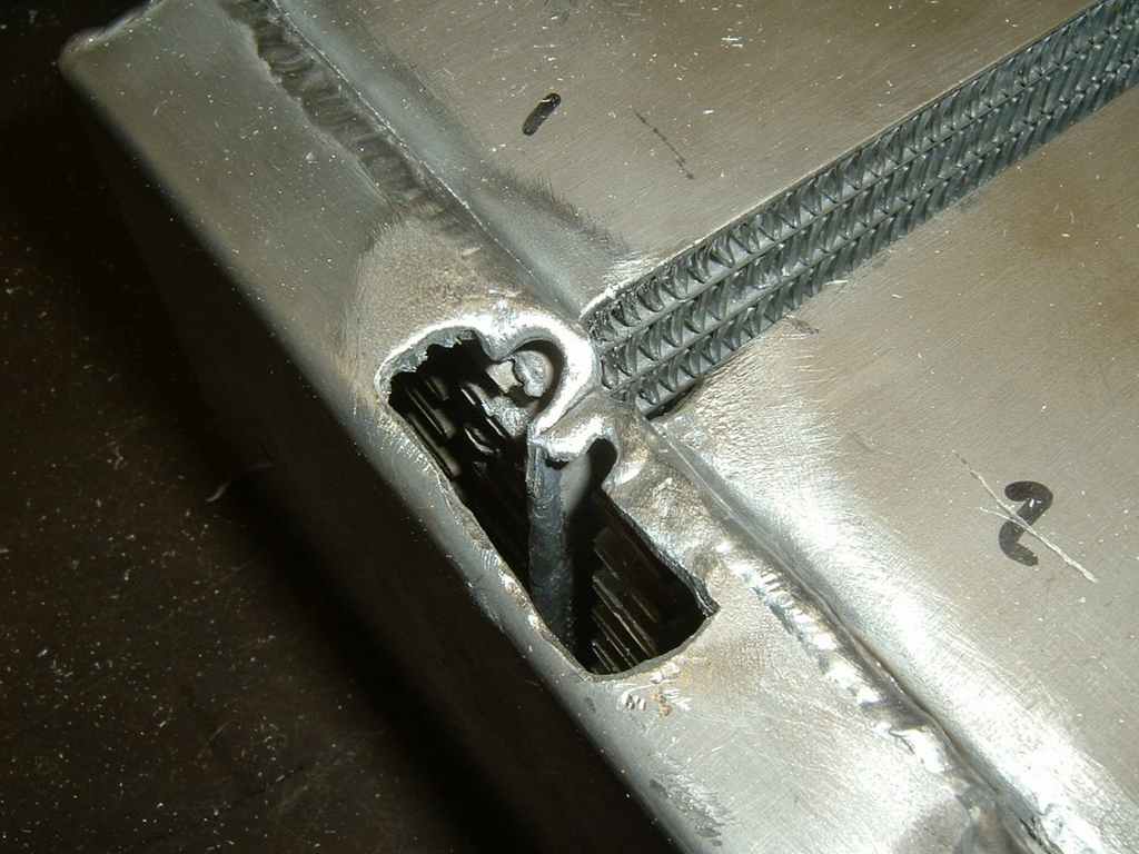
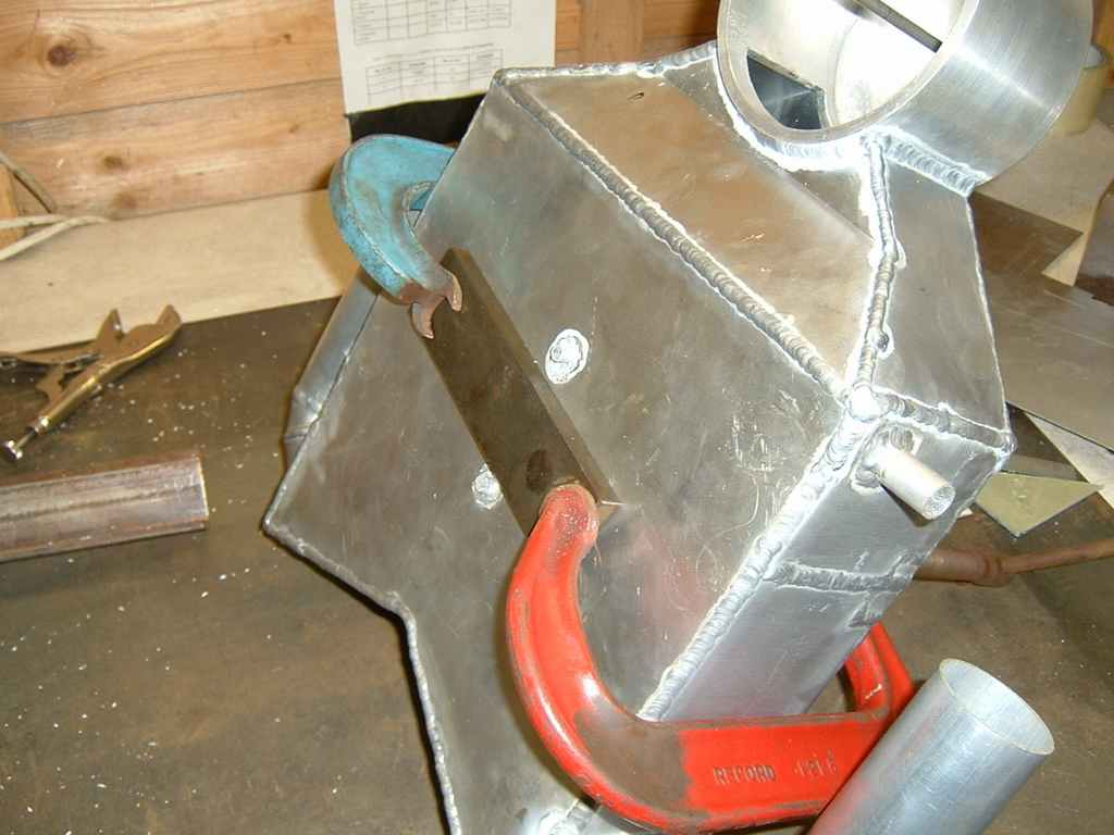
When I originally fitted the dowel rods that prevent the charge tank from ballooning,
I didn't clamp the assembly together -
Drill press used with a centre to ensure the tap goes in straight. I used a 3/8 BSP which is fairly close to the 3/8 NPTF for the air temp sensor.
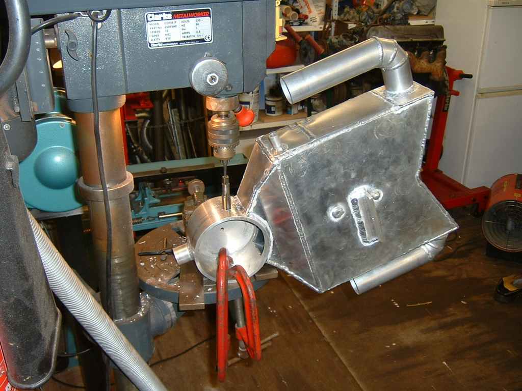
All welding completed. Pressure tested the charge side, no leaks at-